Cortex M4 Technical Reference Manual
ISD Series Datasheet Page 1 of 109 Rev113 I SD 0 T ISD ARM® Cortex®M4F SoC ISD Series Datasheet The information described in this document is the exclusive intellectual property of22 Block diagram Figure 21 GD32F330xx block diagram e e NVIC m TPIU SW Flash Memory Controller Flash Memory x SRAM Controller SRAM AHB to APB Bridge 2 GP DMA 7chs USART0 SPI 0 ADC TIMER16 12bit SAR ADC IBus ARM CortexM4 Processor F max 84MHz POR/PDR PLL Fmax 84 MHz LDO 12V IRC8M 8MHz HXTAL 432MHz LVD EXTI TIMER0 AHB1 Fmax = 84 MHz
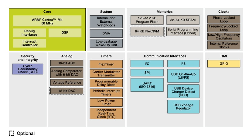
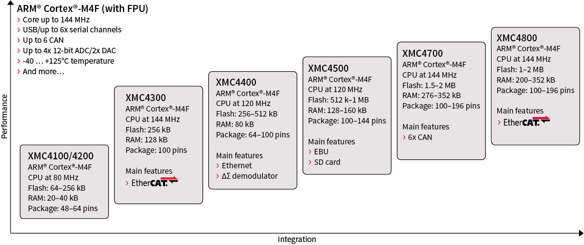
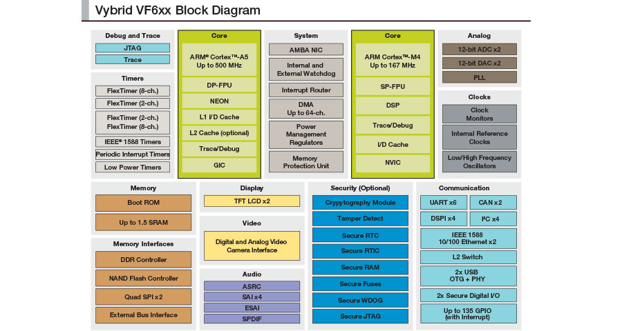
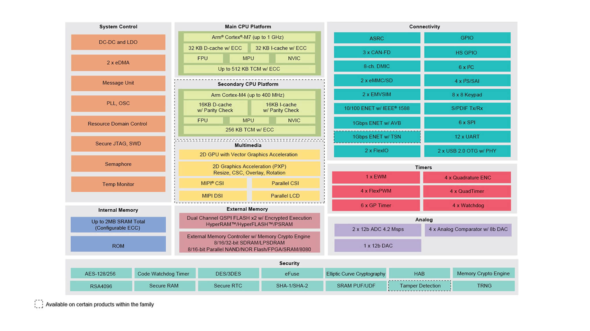
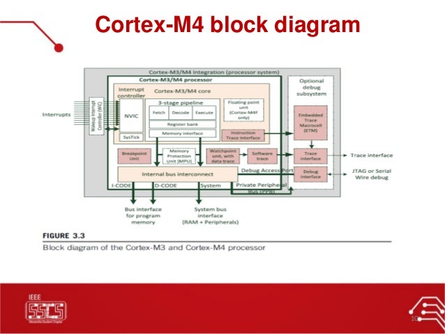
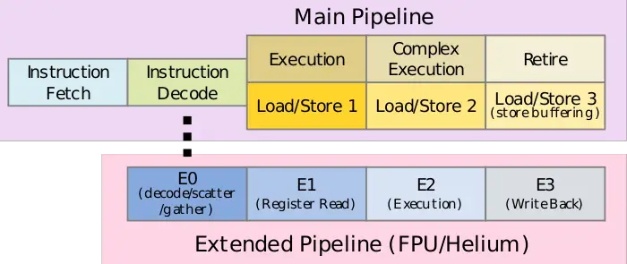
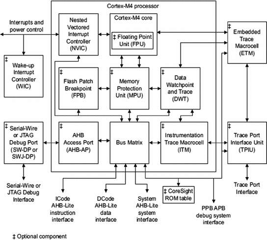
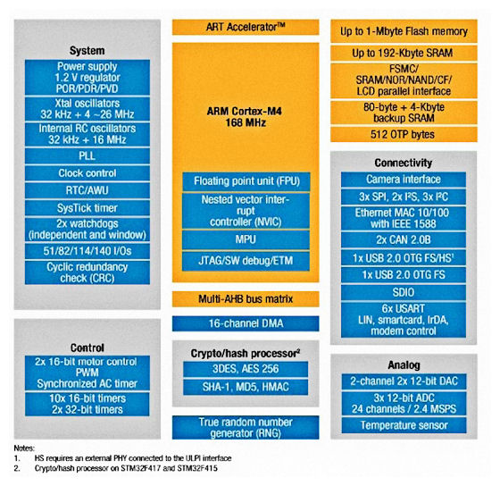
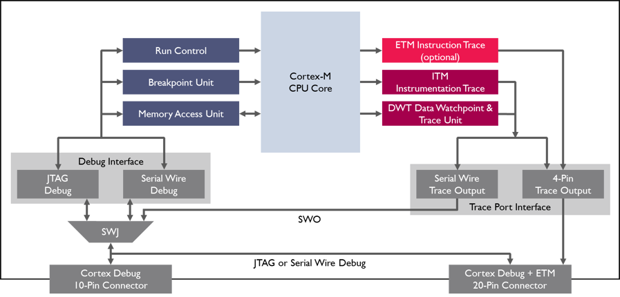
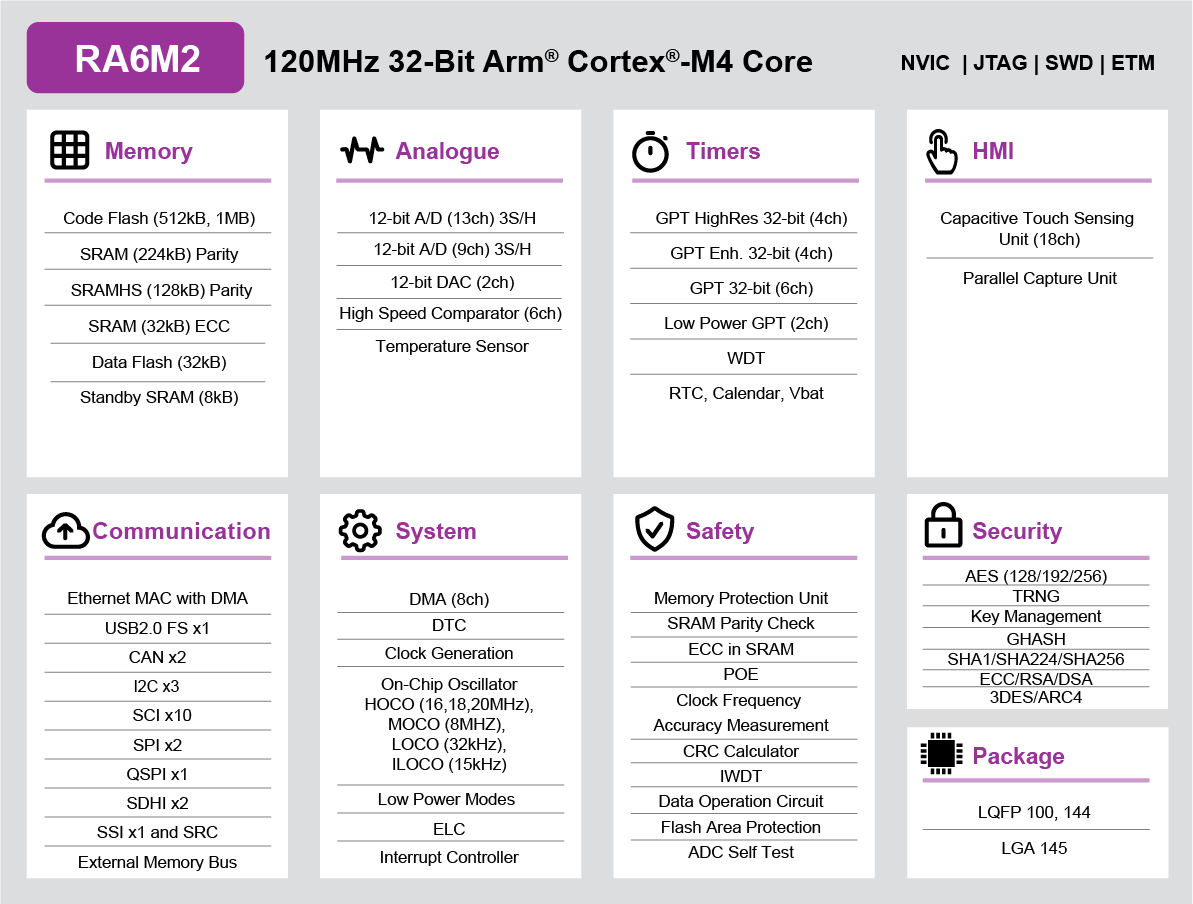
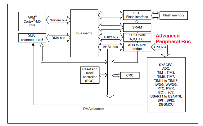
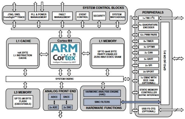
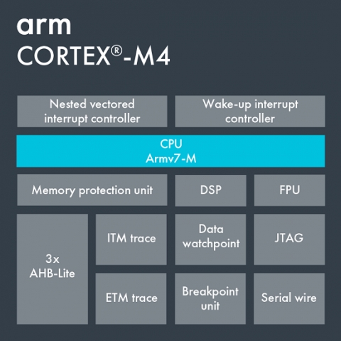
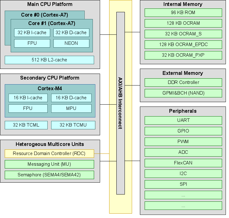
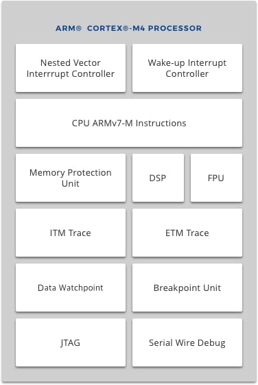
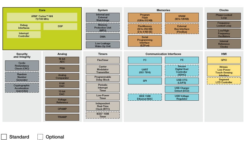
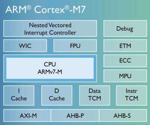
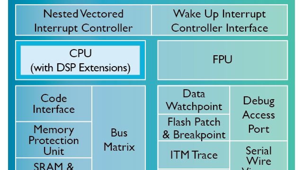
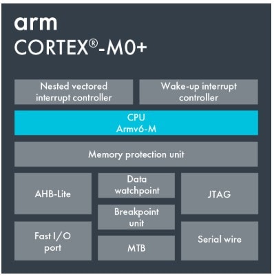
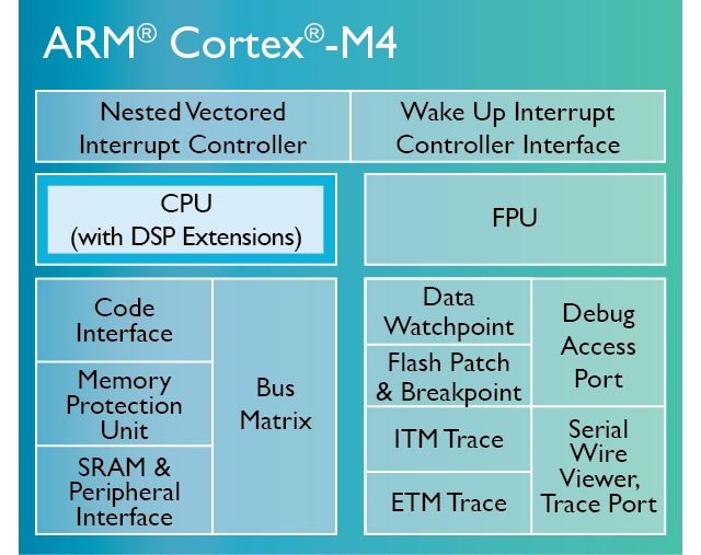
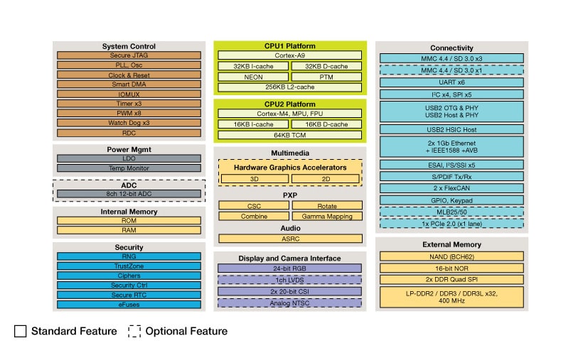
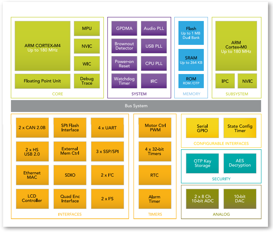
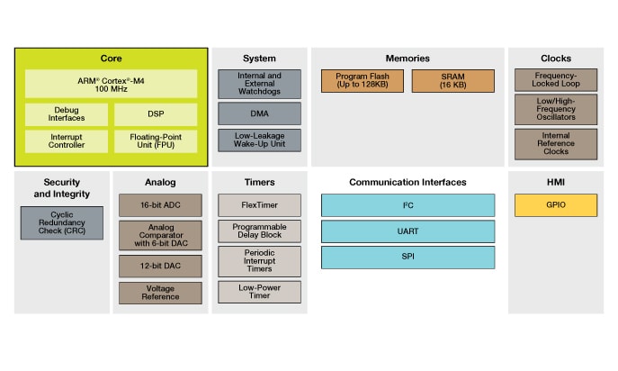
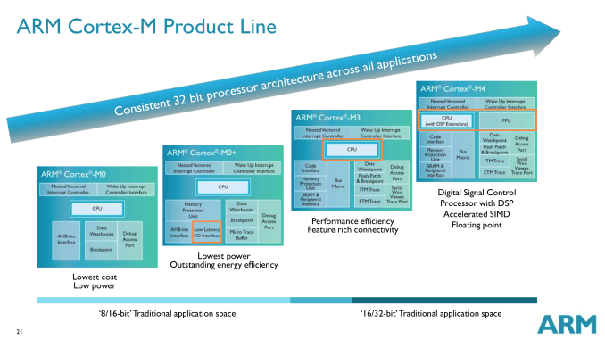
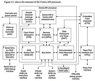
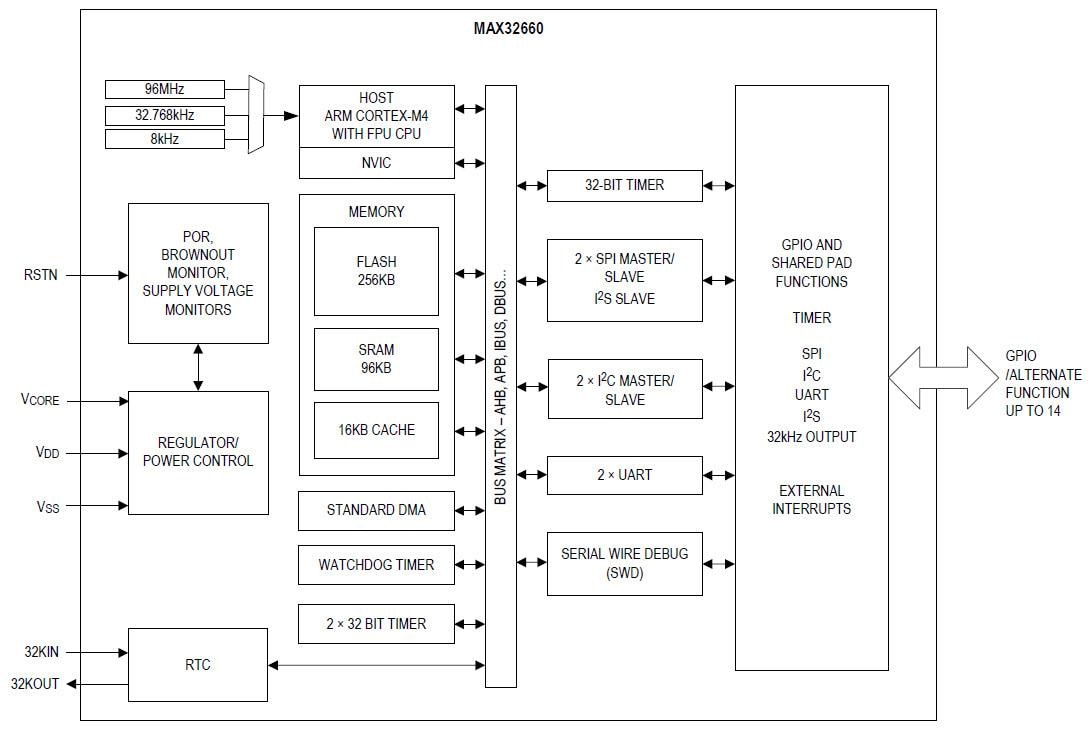
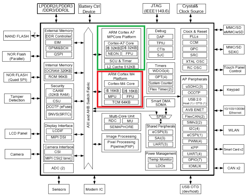
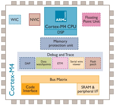
Arm cortex m4 block diagram
Arm cortex m4 block diagram-Based on the ARM CortexM4 Romulo Ant´ ao, Alexandre Mota, Rui Escadas Martins˜ Dept Eletronica, Telecomunicac¸´ oes e Inform˜ ´atica Universidade de Aveiro, Portugal fromuloantao, alex, rmmg@uapt Abstract—The versatility and closedloop performance resulting from the use of selfcalibrating control systems are two ofFigure 21 GD32F307xx block diagram 32bit ®generalpurpose microcontroller based on the ARM® Cortex M4 RISC core with best costperformance ratio in terms of enhanced processing capacity, reduced power consumption and peripheral set
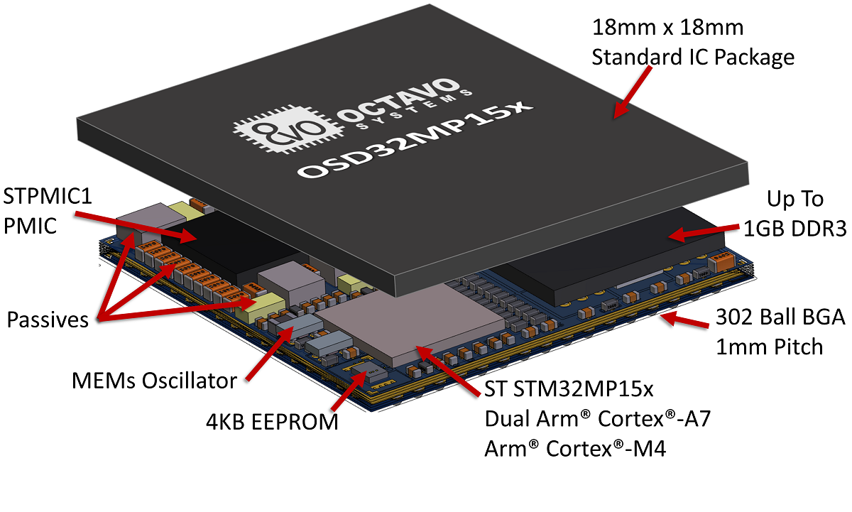
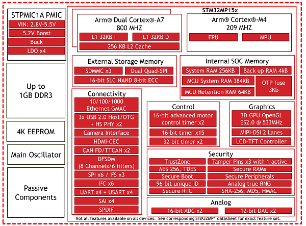
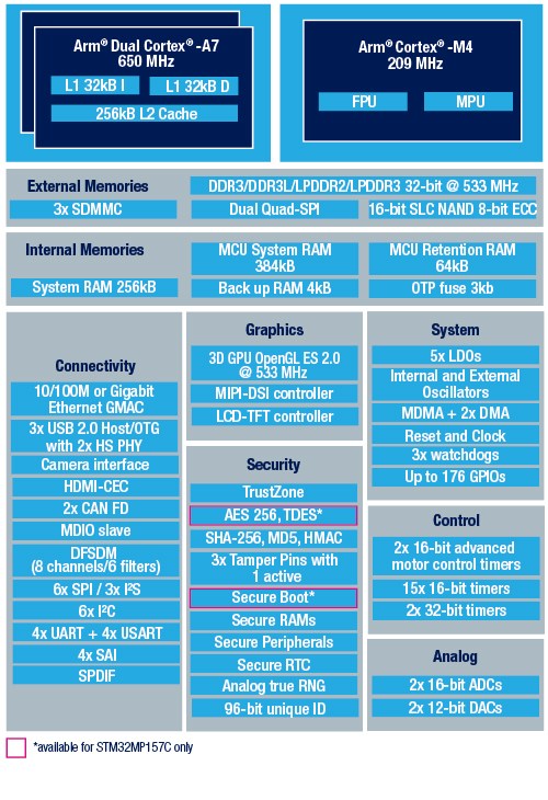
Stm32mp1 Module Octavo Systems Osd32mp15x System In Package
The Arm® Cortex®M33 core processor is designed for IoT and embedded applications that require efficient security or digitalsignal control The processor has many optional features including a digital signal processing extension (DSP), TrustZone security for hardwareenforced isolation, memoryprotection units (MPUs) and a floatingpoint unit (FPU)Documentation – Arm Developer FeedbackBlock diagram 9 23 Pinouts and pin assignment The GD32F305xx device incorporates the ARM® Cortex®M4 32bit processor core operating at 1 MHz frequency with Flash accesses zero wait states to obtain maximum efficiency It
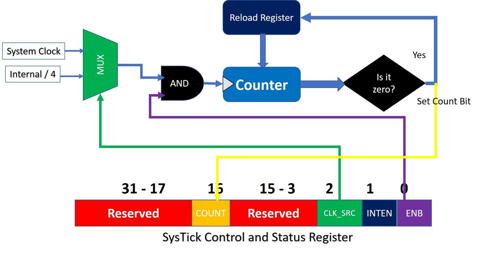
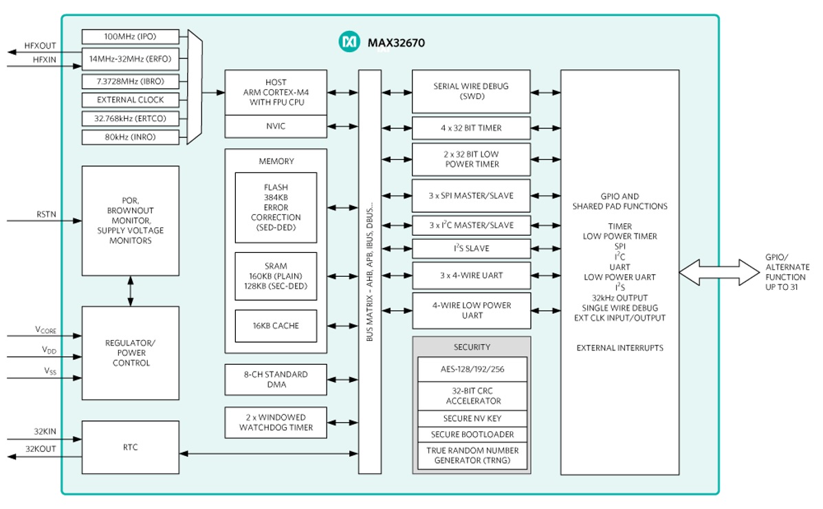
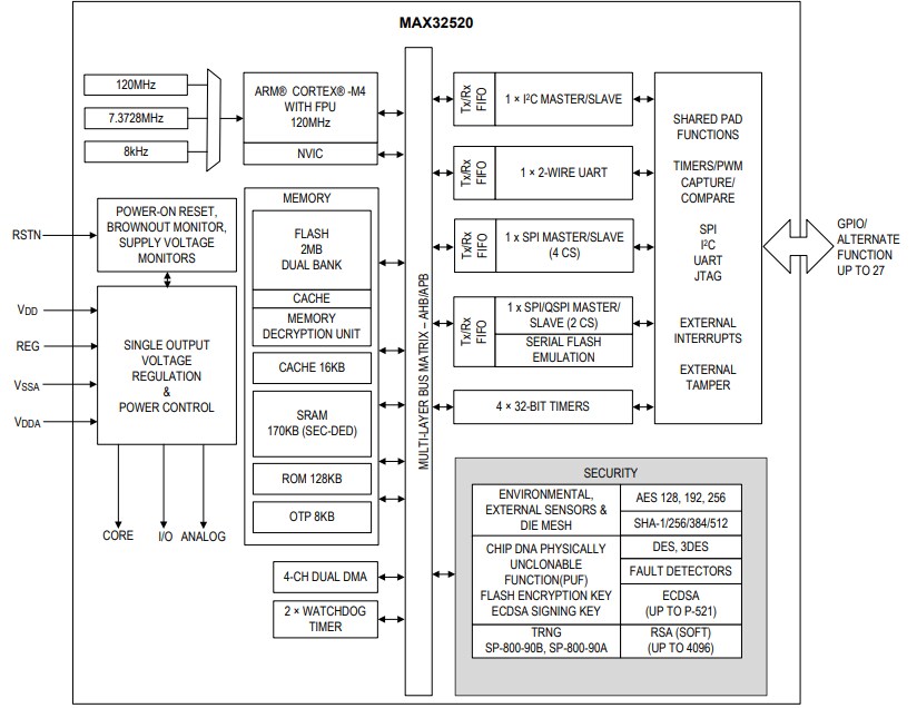
TM4C123GH6PM ARM Cortex M4 microcontroller provides a 24bit system timer that supports down decrement feature That means it counts downwards starting from a preloaded or set value The rate of value decrement depends on the system clock frequency and we can set the value of clock frequency using a control register which is associated with the Systick timerARM® Cortex®M3 & M4 MCU Architecture Introduction Many embedded developers are familiar with the ARM Cortex processor architecture, but few have the opportunity to become intimately acquainted enough of this popular architecture to take fullTimer Block Diagram, MAX325 ChipDNA Secure Arm Cortex M4 Microcontroller MAX325 ChipDNA Secure Arm Cortex MAX325 10 UART TIMER — UART DeepCover embedded security solutions cloak sensitive data under multiple layers of advanced physical security Arm CortexM4 with FPU Processor
Arm cortex m4 block diagramのギャラリー
各画像をクリックすると、ダウンロードまたは拡大表示できます
 | ||
 |  |  |
 | ||
「Arm cortex m4 block diagram」の画像ギャラリー、詳細は各画像をクリックしてください。
 |  |  |
 |  |  |
 |  |  |
「Arm cortex m4 block diagram」の画像ギャラリー、詳細は各画像をクリックしてください。
 |  |  |
 |  |  |
 |  |  |
「Arm cortex m4 block diagram」の画像ギャラリー、詳細は各画像をクリックしてください。
 |  | |
 |  | |
 |  | |
「Arm cortex m4 block diagram」の画像ギャラリー、詳細は各画像をクリックしてください。
 |  |  |
 |  |  |
 |  |  |
「Arm cortex m4 block diagram」の画像ギャラリー、詳細は各画像をクリックしてください。
 | ||
 |  |  |
 |  | |
「Arm cortex m4 block diagram」の画像ギャラリー、詳細は各画像をクリックしてください。
 |  | |
 |  |  |
 |  |  |
「Arm cortex m4 block diagram」の画像ギャラリー、詳細は各画像をクリックしてください。
 |  |  |
 | ||
 |  | |
「Arm cortex m4 block diagram」の画像ギャラリー、詳細は各画像をクリックしてください。
 |  | |
 |  |  |
 | ||
「Arm cortex m4 block diagram」の画像ギャラリー、詳細は各画像をクリックしてください。
 |  | |
 |  |  |
 | ||
「Arm cortex m4 block diagram」の画像ギャラリー、詳細は各画像をクリックしてください。
 |  | |
 |  |  |
 |  | |
「Arm cortex m4 block diagram」の画像ギャラリー、詳細は各画像をクリックしてください。
 |  |  |
 |
The GD32F303xx device incorporates the Arm® Cortex®M4 32bit processor core operating at 1 MHz frequency with Flash accesses zero wait states to obtain maximum efficiency It provides up to 3072 KB onchip Flash memory and 96 KB SRAM memory An extensive range of enhanced I/Os and peripherals connected to two APB buses Block Diagram of LPC1768 The following image shows the internal block diagram of the LPC1768 MCU As you can see from the block diagram, the ARM CortexM3 Processor consists of three buses Icode bus (for Instruction Fetch), Dcode bus (for Data Access) and System Bus (for peripheral access)


0 件のコメント:
コメントを投稿